System Concepts for Solar Space Heating of Industrial Buildings
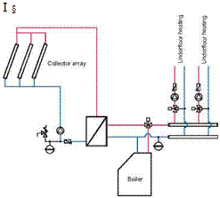
In most solar space heating systems applied in factory buildings, standard system concepts have been used - collectors heat a storage tank that feeds into an underfloor heating system (see Figure
3).
 |
 |
 |
 |
Another option would be to use the thermal mass of the concrete floor of the building, which has a large storage capacity, to replace the storage tank entirely (see Figure 4). This is possible because most industrial buildings have a relatively thick concrete floor and the required room temperatures are typically lower than in residential buildings.
Figure 3. System concept with storage tank. Figure 4. Hydraulic layout without storage tank,
the concrete slab is used to store solar heat.
An additional step to simplify the system would be to abandon the heat exchanger and to fill the entire system with antifreeze fluid. The disadvantage of this concept is that a large quantity of antifreeze fluid is needed depending on the size of the building. The anti-freeze fluid is expensive and has to be replaced from time to time. On the other hand, the cost of the heat exchanger can be saved and there is no loss in temperature from the collector to the space-heating loop due to the heat exchanger.
If the concrete floor is used to store heat, it should be charged whenever there is heat available from the collectors even if the room temperature is already reached. This way, the storage capacity of the floor can be best used. Of course, both room temperature and floor temperature should not pass certain specified limits. The European standard EN 1264 states maximum floor surface temperatures of 29°C in the central part of the floor surface and 35°C in the peripheral zone. These temperatures are determined by physiological considerations.
The dimensioning guidelines presented are based on simulations [1] of the reference buildings with different heating system concepts and system sizes (collector areas 100 - 400 m2). Weather data for Graz, Austria and a standard flat plate collector [po=0.8, c1=3.5 W/(m2K), c2=0.015 W/(m2 K)] were used. To avoid detailed simulation calculations in the pre-planning phase, generally applicable dimensioning nomograms were developed to allow a rapid and reliable estimate of the collector area and the solar storage tank volume for space heating applications in factory buildings.
Apart from the key data for the solar thermal system, the solar fraction to be expected for the project in question and the specific solar yield can be read off the nomogram. The solar fraction is defined as
![]()
![]() Solar Fraction = 1 -
Solar Fraction = 1 -
Qconv
where Qaux Energy delivered by the auxiliary heating system, kWh/a
Qconv Energy needed for space heating without the solar thermal system, kWh/a
To simplify the use of nomograms, the "utilization ratio" is defined as an important auxiliary characteristic number. This is a measure for the dimensioning of solar thermal systems and describes the ratio of annual consumption to the collector area.
Annual heat requirement kWh
Utilization ratio = [ ]
total heat requirement a • m^
Gross collector area
It should be remembered that the following nomograms are only suitable for the design of solar thermal systems in factory buildings similar to the calculated reference cases and for similar boundary conditions. All cases were calculated based on the assumption that the set room temperature of 16°C has to me met at all times. If for example at night or at the weekend lower room temperatures can be tolerated, higher solar fractions are possible.