Concrete Floor Slab as Heat Store
Simulations were carried out for concrete slabs of 20, 40 and 60 cm thickness. However, the piping of the underfloor heating system was always installed at a depth of 10 cm. The floor thickness shows only a small sensitivity with respect to the solar fraction that can be reached with the system. Doubling or even tripling the floor thickness leads to an increase in solar fraction of only a few percentage points. Therefore, a floor thickness around 30-50 cm is a reasonable value. Floor slabs in this order of magnitude are commonly used in many industrial buildings anyway.
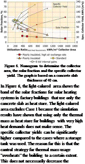
When the results are plotted against the utilization ratio, as it was done for the system concept with storage tank, the points scatter significantly more (see Figure 6). The highest solar fractions are obtained with the standard reference case. In Case 4 (8 kW internal gains), solar fractions are lower because during the day the machine operation leads to high air temperatures and high floor temperatures, therefore the solar thermal system cannot store much heat in the concrete mass. In this case, using the thermal mass as a storage tank is particular unfavorable because the solar energy cannot be stored to be used during the night. In Case 2 (poorly insulated), solar fractions are again lower. In this case, the overall heat demand of the building is much higher and as a result the conventional heating system is turned on more often. The conventional heating system also uses the underfloor heating system, which leads to higher average floor temperatures. If this is the case, then the potential for solar heat to be stored in the floor is decreased, which in turn decreases the solar fraction that can be reached. This effect is even more pronounced in Case 1 (poorly insulated and high air exchange rate). In this case, the overall heat demand of the building is so high that the
 |
conventional heating system has to be turned on almost all the time. Therefore, solar fractions are decreased dramatically.
Regarding the nomogram for systems using the concrete slab as heat store, it is even more important to remember that the results shown can only give a rough approximation of the solar fractions that can be reached. The results are only strictly valid for the reference buildings described above. Systems without water store are even more sensitive to a change of boundary conditions as could be shown with the different reference cases considered. If for example, a building is much higher than the reference buildings or a higher air temperature is required, this can have a strong influence on the function of the concrete slab as a heat store. It not only increases the heat demand of the building but also decreases the solar fraction that can be reached. Therefore, a more detailed simulation of the building and the heating system may be necessary if the thermal mass is to be used as the only heat store.
As for systems that use a water storage tank, systems should be designed in accordance with the optimum cost-to-benefit ratio (orange area, degrees of solar fraction of the overall heating requirement between 15 and 30%). Degrees of solar fraction of less than 15% are outside the cost- to-benefit optimum since the (slight) rise in the specific yield does not make up for the higher specific system costs of a smaller solar thermal system and would thus lead to higher solar heating costs.