Solar thermal collectors and applications
Thermal analysis of collectors
In this section the thermal analysis of the collectors is presented. The two major types of collectors, i. e. flat-plate and concentrating are examined separately. The basic parameter to consider is the collector thermal efficiency. This is defined as the ratio of the useful energy delivered to the energy incident on the collector aperture. The incident solar flux consists of direct and diffuse radiation. While FPC can collect both, concentrating collectors can only
|
utilise direct radiation if the concentration ratio is greater than 10 [96].
3.1. Flat-plate collectors performance
|
|
|
The fin, shown in Fig. 13(a) is of length L = (W — D)/2. An elemental region of width Dx and unit length in the flow direction is shown in Fig. 13(b). An energy balance on this element gives
|
|
 |
|
In this section various relations that are required in order to determine the useful energy collected and the interaction of the various constructional parameters on the performance of a collector are presented.
Under steady-state conditions, the useful heat delivered by a solar collector is equal to the energy absorbed by the heat transfer fluid minus the direct or indirect heat losses from the surface to the surroundings. The useful energy collected from a collector can be obtained from the following formula:
qu = Ac[Gt™ — UL(Tp — Ta)] = mcplTo — Ti] (1)
Eq. (1) can be modified by substituting inlet fluid temperature (Ti) for the average plate temperature (Tp), if a suitable correction factor is included. The resulting equation is
qu = AcFR[Gt(ra) — Ul(T, — Ta)] (2)
|
|
|
|
|
|
|
where S is the absorbed solar energy. By dividing through with Dx and finding the limit as Dx approaches zero, gives:
|
|
|
|
 |
|
|
|
The two boundary conditions necessary to solve this second-order differential equation are:
|
|
 |
|
|
|
For convenience the following two variables are defined:
|
|
|
where FR is the correction factor, or collector heat removal factor.
Heat removal factor can be considered as the ratio of the heat actually delivered to that delivered if the collector plate were at uniform temperature equal to that of the entering fluid. In Eq. (2) the temperature Ti of the inlet fluid depends on the characteristics of the complete solar heating system and the hot water demand or heat demand of the building. However, FR is affected only by the solar collector characteristics, the fluid type, and the fluid flow rate through the collector. FR may be obtained from Ref. [97]
|
|
|
|
|
|
|
|
|
|
|
Therefore, Eq. (5) becomes
|
|
|
|
|
which has the boundary conditions: dC
|
|
 |
|
|
 |
|
Eq. (8) is a second-order homogeneous linear differential equation whose general solution is:
C = C e”™ + C2 e mx = C1 sinh(mx) + C2 cosh(mx) (9)
|
|
|
|
|
where F' is the collector efficiency factor. It represents the ratio of the actual useful energy gain that would result if the collector-absorbing surface had been at the local fluid temperature.
The collector efficiency factor can be calculated by considering the temperature distribution between two pipes of the collector absorber and by assuming that the temperature gradient in the flow direction is negligible [97]. This analysis can be performed by considering the sheet tube configuration shown in Fig. 13, where the distance between the tubes is W, the tube diameter is D, and the sheet thickness is S. As the sheet metal is usually made from copper or aluminum which are good conductors of heat, the temperature gradient through the sheet is negligible, therefore the region between the centerline separating the tubes and the tube base can be considered as a classical fin problem.
|
|
|
The first boundary yields C1 = 0, and the second boundary condition yields:
S
C = Tb — Ta — — = C2 cosh(mL) or
UL
|
|
|
C = Tb — Ta — S/Ul 2 cosh(mL)
With C1 and C2 known, Eq. (9) becomes:
|
|
|
T — Ta — S/Ul Tb — Ta — S/Ul
|
|
|
|
|
|
|
This equation gives the temperature distribution in the x-direction at any given y.
The energy conducted to the region of the tube per unit length in the flow direction can be found by evaluating
|
|

SHAPE * MERGEFORMAT

|
tanh [m(W - D)/2]
m(W - D)/2
|
|
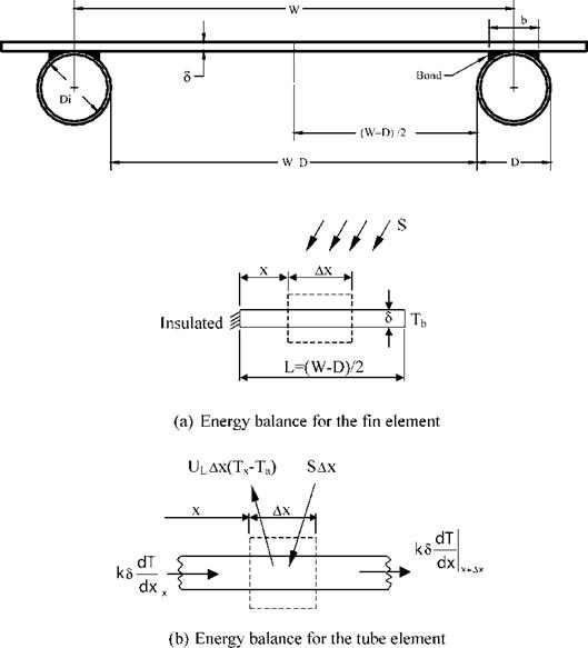
Fig. 13. Flat-plate sheet and tube configuration.
|
|
|
where factor F in Eq. (13) is the standard fin efficiency for straight fins with rectangular profile, obtained from:
|
|
|
the Fourier’s law at the fin base:
|
|
 |
|
~—[S - UL(Tb - Ta)]tanh(mL) (11)
UL
|
|
 |
|
|
|
but k dm/UL is just 1/m. Eq. (11) accounts for the energy collected on only one side of the tube; for both sides, the energy collection is
|
|
|
The useful gain of the collector also includes the energy collected above the tube region. This is given by:
|
|
SHAPE * MERGEFORMAT

|
qfin = (W - D)[S - Ul(Tb - Ta)]
|
![Подпись: qfin = (W - D)[S - UL(Tb - Ta)]](/img/1124/image045.gif)

tanh [m(W - D)/2]
m(W - D)/2
or with the help of fin efficiency
qtube = D[S - Ul (Tb - Ta)] (15)
Accordingly, the useful energy gain per unit length in the direction of the fluid flow is:
|
qfin = (W - D)F [S - Ul (Tb - Ta)]
|
![Подпись: qfin = (W - D)F [S - UL (Tb - Ta)]](/img/1124/image047.gif) (13) q'u = qfin + qtube = [(W - D)F + D][S - Ul (Tb - Ta)] (16)
(13) q'u = qfin + qtube = [(W - D)F + D][S - Ul (Tb - Ta)] (16)
|
This energy must be ultimately transferred to the fluid, which can be expressed in terms of two resistances as:
|
|
hw = 5.7 + 3.8W (24)
f = (1 - 0.04hw + 0.0005hw)(1 + 0.091Ng) (25)
C = 365.9(1 - 0.00883b + 0.0001298b2) (26)
|
|
1 | 1 |
Ul[D + (W - D)F] + Cb + pD,
|
|
ST2 + Ta2)(Tav + Ta)
1 2Ng + f - 1
ip + 0.05Ng(1 - £p) £g
|
|
The bond conductance can be very important in accurately describing the collector performance and generally it is necessary to have good metal-to-metal contact so that the bond conductance is greater that 30 W/m K and preferably the tube should be welded to the fin.
Solving Eq. (17) for Tb, substituting it into Eq. (16) and solving the result for the useful gain, we get
qu = WF'[S - UL(Tf - Ta)] (19)
|
 |
|
i. e. it is the heat transfer resistance from the absorber plate to the ambient air.
In addition to serving as a heat trap by admitting shortwave solar radiation and retaining longwave thermal radiation, the glazing also reduces heat loss by convection. The insulating effect of the glazing is enhanced by the use of several sheets of glass, or glass plus plastic. The top loss coefficient in Eq. (22) is given by [98]:
|
|
|
In Eq. (17), Cb is the bond conductance which can be estimated from knowledge of the bond thermal conductivity kb, the average bond thickness y, and the bond width b. The bond conductance on a per unit length basis is given by:
|
|
 |
 |
|
|
|
|
 |
|
where the collector efficiency factor F' is given by:
|
|
|
and Tp is the collector stagnation temperature, i. e. the temperature of the absorbing plate when the flow rate is equal to zero, and is obtained from:
|
|
 |
|
|
 |
|
A physical interpretation of F' is that it represents the ratio of the actual useful energy gain to the useful energy gain that would result if the collector absorbing surface had been at the local fluid temperature. It should be noted that the denominator of Eq. (20) is the heat transfer resistance from the fluid to the ambient air. This resistance can be represented as 1/Uo. Therefore, another interpretation of F' is:
|
|
|
|
|
As usually good insulation is used in the collector construction, the loss coefficient for the bottom and edges of the collector, Ub and Ue, in Eq. (22) is constant, and its estimation is straightforward. The heat loss from the back of the plate rarely exceeds 10% of the upward loss.
The overall transmittance-absorptance product (та) is determined as:
|
|
|
|
|
|


The collector efficiency factor is essentially a constant factor for any collector design and fluid flow rate. The ratio of UL to Cb, the ratio of UL to hfi, and the fin efficiency F are the only variables appearing in Eq. (20) that may be functions of temperature. For most collector designs F is the most important of these variables in determining F0 . The factor F0 is a function of UL and hfi, each of which has some temperature dependence, but it is not a strong function of temperature. Additionally, the collector efficiency factor decreases with increased tube center-to-center distances and increases with increases in both material thicknesses and thermal conductivity. Increasing the overall loss coefficient decreases F0 while increasing the fluid-tube heat transfer coefficient increases F0.
The overall heat loss coefficient is a complicated function of the collector construction and its operating conditions and it is given by the following expression
Ul = Ut + Ub + Ue (22)
1 + cos b
IbT (™)b + b 2 (ra)s + P1'
I
(28)
Finally, the collector efficiency can be obtained by dividing qu by (GtAc). Therefore,
n = Fr[та - ] (29)
For incident angles below about 35°, the product т times a is essentially constant and Eqs. (2) and (29) are linear with respect to the parameter (Ti - Ta)/Gt, as long as UL remains constant.
In reality the heat loss coefficient UL in Eqs (2) and (42) is not constant but is a function of collector inlet and ambient temperatures. Therefore: TOC o "1-5" h …
The term greenhouse effect has generally been used for the role of the whole atmosphere (mainly water vapour and clouds) in keeping the surface of the earth warm. Recently however, …
Simulations are powerful tools for process design offering a number of advantages as outlined in the previous sections. However, there are limits to their use. For example, it is easy …