Solar thermal collectors and applications
Minimum entropy genчeration rate
The minimization of the entropy generation rate is the same as the maximization of the power output. The process of solar energy collection is accompanied by the generation of entropy upstream of the collector, downstream of the collector and inside the collector as shown in Fig. 18.
|
By using Eqs. (52) and (53), Eq. (55) can be written as: |
|
Sgen T (Ex, in Ex, out) To |
|
(56) |
|
Fig. 18. Exergy flow diagram. |
|
or Ex, out = Ex, in - ToSgen (57) Therefore, if we consider Ex, in constant, the maximisation of the exergy output (Ex, out) is the same as the minimisation of the total entropy generation Sgen. |
|
3.3.2. Optimum collector temperature By substituting Eqs (46) and (47) into Eq. (55) the rate of entropy generation can be written as: |
|
S |
|
gen |
|
UrAr (Tr - To) To |
|
Qp Qp - UrAr (Tr - To) T, + Tr |
|
(58) |
|
By applying Eq. (50) in Eq. (58) and by performing various manipulations: |
|
Sgen u __ 2 __ qoC Umax UrAr nO Ur T, U |
|
(59) |
|
The dimensionless term Sgen/UrAr accounts for the fact that the entropy generation rate scales with the finite size of the system which is described by Ar = Aa=C. By differentiating Eq. (59) with respect to U and setting to zero the optimum collector temperature (Uopt) for |
 |
Considering that C = Aa/Ar, then:
qOC
По Ur To
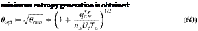
As can be seen from Eq. (50), Umax is proportional to C, i. e. the higher the concentration ratio of the collector the higher is Umax and Tr, max. The term Tr, max in Eq. (48) is also known as the stagnation temperature of the collector, i. e. the temperature that can be obtained at no flow condition. In dimensionless form the collector temperature U = Tr/TO will vary between 1 and Umax, depending on the heat delivery rate Q. The stagnation temperature Umax is the parameter that describes the performance of the collector with regard to collector-ambient heat loss as there is no flow through the collector and all the energy collected is used to raise the temperature of the working fluid to stagnation temperature which is fixed at a value corresponding to the energy collected equal to energy loss to ambient. Thus the collector efficiency is given by:
The exergy inflow coming from the solar radiation falling on the collector surface is:
Ex, in = Q*( 1 - TO) (52)
where T, is the apparent sun temperature as an exergy source. In this analysis the value suggested by Petela [107] is adopted, i. e. T, is approximately equal to 3/4Ts, where Ts is the apparent black body temperature of the sun, which is about 6000 K. Therefore, T, considered here is 4500 K. It should be noted that in this analysis T, is also considered constant and as its value is much greater than TO, Ex, in is very near Q. The output exergy from the collector is given by:
Ex, out = q( 1 - To) (53)
whereas the difference between the Ex, in — Ex, out represents the destroyed exergy. From Fig. 18, the entropy generation rate can be written as:
|
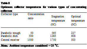
Optimum collector temperatures for various types of concentrating collectors
Notes: Ambient temperature considered = 25 0C. |
|
minimum entropy generation is obtained: |
|
(61) |
![]()
|
(64) |
![]()
 By subtkutmg Umax by Tr, max=To and Uopt by Tr, opt=To; Eq. (60) can be written as:
Tr, opt VTr, max To
This equation states that the optimal collector temperature is the geometric average of the maximum collector (stagnation) temperature and the ambient temperature. Typical stagnation temperatures and the resulting optimum operating temperatures for various types of concentrating collectors are shown in Table 8. The stagnation temperatures shown in Table 8 are estimated by considering mainly the collector radiation losses.
As can be seen from the data presented in Table 8 for high performance collectors, like the central receiver, it is better to operate the system at high flow rates in order to lower the temperature around the value shown instead of operating at very high temperature, in order to obtain higher thermodynamic efficiency from the collector system.
By applying Eq. (60) to Eq. (59), the corresponding minimum entropy generation rate is:
Sgen, min 2Г Га 14 Umax 1 /624
= 2( u™x 2 1) 2 —^ (62)
where U* = T*=To. It should be noted that for flat-plate and low concentration ratio collectors, the last term of Eq. (62) is negligible as U* is much bigger than Umax — 1, but it is not for higher concentration collectors, like the central receiver and the parabolic dish ones, which have stagnation temperatures of several thousands of degrees.
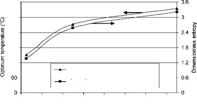
By applying the stagnation temperatures shown in Table 8 to Eq. (62), the dimensionless entropy generated against the collector concentration ratios considered here as shown in Fig. 19 is obtained.
3.3.3. Non-isothermal collector
So far the analysis was carried out by considering an isothermal collector. For a non-isothermal one, which is a more realistic model particularly for the long PTC, and by applying the principle of energy conservation:
TOC o "1-5" h z q* = Ur (T — T0 ) + mcp d - (63) where x is from 0 to L (the collector length). The generated entropy can be obtained from:
Tout Q* Qo
Sgen = mcp ln - TfT - 2 - Tf + - ZT
Tin T T o
From an overall energy balance, the total heat loss is: Qo = Q* — mcp (Tout — Tin) (65)
Substituting Eq. (65) into Eq. (64) and performing the necessary manipulations the following relation is obtained:
|
540 |
|
450 |
|
360 |
|
270 |
|
180 |
|
Optimum temperature (°С) |
|
Dimensionless entropy [from Eq. (62)] |
|
0 200 400 600 800 1000 1200 1400 Concentration ratio Fig. 19. Entropy generated and optimum temperatures against collector concentration ratio. |
 |
Ns = ln Up — Uout + Un) — d + 1 (66)