Solar thermal collectors and applications
3.2.2. Thermal analysis
The generalised thermal analysis of a concentrating solar collector is similar to that of a FPC. It is necessary to derive appropriate expressions for the collector efficiency factor F, the loss coefficient UL and the collector heat removal factor FR. For the loss coefficient standard heat transfer relations for glazed tubes can be used.
The instantaneous efficiency of a concentrating collector may be calculated from an energy balance of its receiver.
 |
 |
manufacture/assembly and/or in the operation of the collector. These can be identified as reflector profile imperfections, misalignment errors and receiver location errors. Random errors are modeled statistically, by determining the standard deviation of the total reflected energy distribution, at normal incidence [102] and are given by:
S = V sun + 4s2lope + Smrror (35)
Non-random errors are determined from a knowledge of the misalignment angle error P (i. e. the angle between the reflected ray from the centre of sun and the normal to the reflector’s aperture plane) and the displacement of the receiver from the focus of the parabola (dr). As reflector profile errors and receiver mislocation along the Y axis essentially have the same effect a single parameter is used to account for both. According to Guven and Bannerot [102] random and non-random errors can be combined with the collector geometric parameters, concentration ratio (C) and receiver diameter (D) to yield error parameters universal to all collector geometries. These are called ‘universal error parameters’ and an asterisk is used to distinguish them from the already defined parameters. Using the universal error parameters the formulation of the intercept factor g is possible [101]:
<Ґ universal non-random error parameter due to
receiver mislocation and reflector profile errors (d* = dr/D)
P* universal non-random error parameter due to
angular errors (P* = PC)
s* universal random error parameter (s* = sC)
C collector concentration ratio [= Aa/Ar]
D riser tube outside diameter (m)
dr displacement of receiver from focus (m)
P misalignment angle error (degrees)
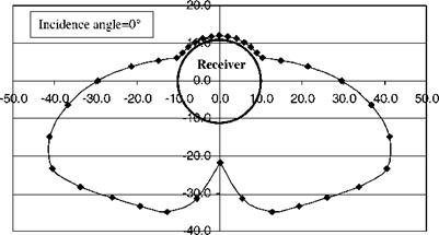
Another parameter that needs to be determined is the radiation concentration distribution on the receiver of the collector, called local concentration ratio (LCR). For the PTC this distribution is as shown in Fig. 14. The shape of the curves depends on the same type or errors mentioned above and on the angle of incidence. Analysis of these effects is presented in Ref. [103] and may not be repeated here. It should be noted that the distribution for half the receiver is shown in Fig. 14. Another more representative way to show this distribution for the whole receiver is shown in Fig. 15. As can be seen from these figures, the top part of the receiver receives essentially only direct sunshine from the sun and the maximum concentration, about 36 suns, occurs at zero incidence angle and at an angle P, shown in Fig. 14, of 120°.
|
Eq. (1) also may be adapted for use with concentrating collectors. Therefore, the useful energy delivered from a concentrator is: qu — Gb noAa — Ar UL (Tr — Ta) (37) |
|
where F' is the collector efficiency factor given by: |
|
F = |
|
1/Ul |
|
Dr |
|
Ul + hfi D, |
|
-+ — + ln D 'i 2k D, |
|
(41) |
 |
|
The useful energy gain per unit of collector length can be expressed in terms of the local receiver temperature Tr as:
' qu Aa no Gb Ar UL
qu = T = L 2~T (T 2 Ta)
Similarly as for the FPC the heat removal factor can be used and Eq. (37) can be written as:
qu = FR IGbnoAa 2 Ar UL(Ti 2 Ta)] (42)
And the collector efficiency can be obtained by dividing qu by (Gb Aa). Therefore,
|
n = fr |
|
no 2 UL |
|
( |
|
Ti 2 Ta |
|
||
|
||
SHAPE * MERGEFORMAT

|
q'u = |
![]()
|
(39) |
![]()
|
D |
![]()
|
o |
![]()

At (T 2 Tf)
hfi d,
If Tr is eliminated from Eqs. (38) and (39) we have: qu = F no Gb 2 U - (Tf 2 Ta)] (40)
where C is the concentration ratio [C = Aa/Ar]. For the FR a relation similar to Eq. (3) is used by replacing Ac to Ar.
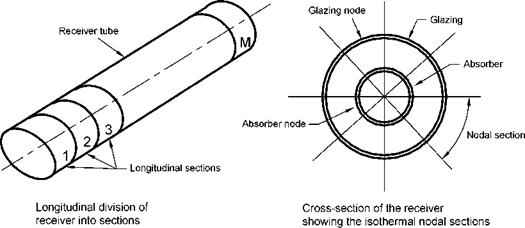
Another analysis usually performed for PTCs is by applying a piecewise two-dimensional model of the receiver by considering the circumferential variation of solar flux shown in Figs. 14 and 15. Such an analysis can be performed by dividing the receiver into longitudinal and isothermal nodal sections as shown in Fig. 16 and applying the principle
|
|
TQp r, max umax = = 1 + |
|
na Q |
|
* |
|
A |
|
a |
|
1 + |
|
(49) |
|
qo Aa no UrAr To |
|
|
|