Solar thermal collectors and applications
Concentrating collectors performance
For concentrating collector both optical and thermal analyses are required.
3.2.1. Optical analysis
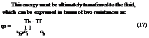
The concentration ratio (C) is defined as the ratio of the aperture area to the receiver/absorber area, i. e.
Aa
C = a (30)
Ar
For FPC with no reflectors, C = 1. For concentrators C is always greater than 1. For a single axis tracking collector the maximum possible concentration is given by [1,97]:
1
![]()
![]()
 sin(0m)
and for two-axes tracking collector [1,97]
![]()
![]()
1
sin2(#m) where 6m is the half acceptance angle. The half acceptance angle denotes coverage of one-half of the angular zone within which radiation is accepted by the concentrator’s receiver. Radiation is accepted over an angle of 26m because radiation incident within this angle reaches the receiver after passing through the aperture. This angle describes the angular field within which radiation can be collected by the receiver without having to track the concentrator.
Eqs. (31) and (32) define the upper limit of concentration that may be obtained for a given collector viewing angle. For a stationary CPC the angle 6m depends on the motion of the sun in the sky. For example, for a CPC having its axis in a N-S direction and tilted from the horizontal such that the plane of the sun’s motion is normal to the aperture, the acceptance angle is related to the range of hours over which sunshine collection is required, e. g. for 6 h of useful sunshine collection 26m = 90° (sun travels 15°/h). In this case Cmax = 1/sin(45°) = 1.41.
For a tracking collector 6m is limited by the size of the sun’s disk, small scale errors and irregularities of the reflector surface and tracking errors. For a perfect collector and tracking system Cmax depends only on the sun’s disk which has a width of 0.53° (320) [97]. Therefore,
For single axis tracking: Cmax = 1/sin(160) = 216
For full tracking: Cmax = 1/sin2(160) = 46 747
It can, therefore, be concluded that the concentration ratio for moving collectors is much higher. However, high accuracy of the tracking mechanism and careful construction of the collector is required with increased concentration ratio as 6m is very small. In practice, due to various errors, much lower values that the above maximum ones are employed.
Another factor that needs to be determined is the incidence angle for the various modes of tracking. This can be about a single axis or about two axes. In the case of single axis mode the motion can be in various ways, i. e. east-west, north-south or parallel to the earth’s axis.
The mode of tracking affects the amount of incident radiation falling on the collector surface in proportion to
the cosine of the incidence angle. The amount of energy falling on a surface of 1 m2 for four modes of tracking for the summer and winter solstices and the equinoxes is shown in Table 6 [64]. The amount of energy shown in Table 6 is obtained by applying a radiation model [12]. This is affected by the incidence angle which is different for each mode.
The performance of the various modes of tracking can be compared to the full tracking mode, which collects the maximum amount of solar radiation, shown as 100% in Table 6. Relations for the estimation of the angle of incidence for the various modes of tracking are given in Table 7.
The optical efficiency is defined as the ratio of the energy absorbed by the receiver to the energy incident on the collector’s aperture. The optical efficiency depends on the optical properties of the materials involved, the geometry of the collector, and the various imperfections arising from the construction of the collector. In equation form [99]:
no = pray[(1 — Af tan(6))cos(6)] (33)
The geometry of the collector dictates the geometric factor Af, which is a measure of the effective reduction of the aperture area due to abnormal incidence effects. For a PTC, its value can be obtained by the following relation [100]:
2 Г W2 #
Af = з Wahp + fWa 1 + - f (34)
The most complex parameter involved in determining the optical efficiency of a PTC is the intercept factor. This is defined as the ratio of the energy intercepted by the receiver to the energy reflected by the focusing device, i. e. parabola [99]. Its value depends on the size of the receiver, the surface angle errors of the parabolic mirror, and solar beam spread.
The errors associated with the parabolic surface are of two types, random and non-random [101]. Random errors are defined as those errors which are truly random in nature and, therefore, can be represented by normal probability distributions. Random errors are identified as apparent changes in the sun’s width, scattering effects caused by random slope errors (i. e. distortion of the parabola due to wind loading) and scattering effects associated with the reflective surface. Non-random errors arise in
Relations for the estimation of the angle of incidence (0) for the various modes of tracking Mode of tracking Incidence angle Remarks
Full tracking cos(0) = 1
Collector axis in N—S axis cos(0) = cos(5)
polar E—W tracking
Collector axis in N—S axis cos(0) = psin2(a) + cos2(5)sin2(h) or
horizontal E—W tracking cos(0) = cos(F)cos(h) + cos(5)sin2(h)
Collector axis in E—W axis cos(0) = p 1 — c о s 2 ( 5) s i n 2 (h) or
horizontal N—S tracking cos(0) = psin2(5) + cos2(5)cos2(h)
This depends on the accuracy of the tracking mechanism.
This mode collects the maximum possible sunshine
For this mode the sun is normal to the collector at equinoxes
(5 = 0°) and the cosine effect is maximum at the solstices.
When more than one collector is used, front collectors cast shadows on adjacent ones
The greatest advantage of this arrangement is that very small shadowing effects are encountered when more than one collector is used. These are present in the first and last hours of the day The shadowing effects of this arrangement are minimal. The principal shadowing is caused when the collector is tipped to a maximum degree south (5 = 23.5°) at winter solstice. In this case the sun casts a shadow toward the collector at the north
Notes: 5: declination angle, h: hour angle, F : zenith angle. Relations to determine these angles can be found in many solar energy books
 |
 |
manufacture/assembly and/or in the operation of the collector. These can be identified as reflector profile imperfections, misalignment errors and receiver location errors. Random errors are modeled statistically, by determining the standard deviation of the total reflected energy distribution, at normal incidence [102] and are given by:
S = V sun + 4s2lope + Smrror (35)
Non-random errors are determined from a knowledge of the misalignment angle error P (i. e. the angle between the reflected ray from the centre of sun and the normal to the reflector’s aperture plane) and the displacement of the receiver from the focus of the parabola (dr). As reflector profile errors and receiver mislocation along the Y axis essentially have the same effect a single parameter is used to account for both. According to Guven and Bannerot [102] random and non-random errors can be combined with the collector geometric parameters, concentration ratio (C) and receiver diameter (D) to yield error parameters universal to all collector geometries. These are called ‘universal error parameters’ and an asterisk is used to distinguish them from the already defined parameters. Using the universal error parameters the formulation of the intercept factor g is possible [101]:
<Ґ universal non-random error parameter due to
receiver mislocation and reflector profile errors (d* = dr/D)
P* universal non-random error parameter due to
angular errors (P* = PC)
s* universal random error parameter (s* = sC)
C collector concentration ratio [= Aa/Ar]
D riser tube outside diameter (m)
dr displacement of receiver from focus (m)
P misalignment angle error (degrees)
Another parameter that needs to be determined is the radiation concentration distribution on the receiver of the collector, called local concentration ratio (LCR). For the PTC this distribution is as shown in Fig. 14. The shape of the curves depends on the same type or errors mentioned above and on the angle of incidence. Analysis of these effects is presented in Ref. [103] and may not be repeated here. It should be noted that the distribution for half the receiver is shown in Fig. 14. Another more representative way to show this distribution for the whole receiver is shown in Fig. 15. As can be seen from these figures, the top part of the receiver receives essentially only direct sunshine from the sun and the maximum concentration, about 36 suns, occurs at zero incidence angle and at an angle P, shown in Fig. 14, of 120°.
 |
|
The useful energy gain per unit of collector length can be expressed in terms of the local receiver temperature Tr as:
' qu Aa no Gb Ar UL
qu = T = L 2~T (T 2 Ta)
Similarly as for the FPC the heat removal factor can be used and Eq. (37) can be written as:
qu = FR IGbnoAa 2 Ar UL(Ti 2 Ta)] (42)
And the collector efficiency can be obtained by dividing qu by (Gb Aa). Therefore,
|
||
|
||

![]()
![]()
![]()
![]()

At (T 2 Tf)
hfi d,
If Tr is eliminated from Eqs. (38) and (39) we have: qu = F no Gb 2 U - (Tf 2 Ta)] (40)
where C is the concentration ratio [C = Aa/Ar]. For the FR a relation similar to Eq. (3) is used by replacing Ac to Ar.
Another analysis usually performed for PTCs is by applying a piecewise two-dimensional model of the receiver by considering the circumferential variation of solar flux shown in Figs. 14 and 15. Such an analysis can be performed by dividing the receiver into longitudinal and isothermal nodal sections as shown in Fig. 16 and applying the principle
|

|
TQp r, max umax = = 1 + |
|
|
|
